My workstation consists of a FreeBSD desktop with dual LCD monitors and a MacBook Pro provided by my current client for anything that requires access to their network. Both monitors had some age on them, so it was only a matter of time before one died. I've used a dual monitor setup for so long that having only one monitor makes me feel... well, half as productive. When my primary monitor finally cashed in its chips a few months ago, that left me not only less productive but also using a very old LCD given that it was my former secondary. I immediately found a great deal on a shiny, new replacement that brought me up to date with a 23.6" 1080p primary monitor. Although I had 2 monitors again, my former primary sitting in the floor waiting to be recycled seemed to be taunting me.
I searched for solutions and found this to be a common issue with LCD monitors. It wouldn't display anything—not even a "no signal" message—and the power light continuously blinked blue. The most common cause seemed to be one or more bad capacitors, but I've never been good with a soldering iron and I had no experience with this kind of repair. Still, given that I had nothing to lose and the dead monitor was better than the one I was using for my secondary, I decided to try my hand at repairing it. If you have a similar issue (or a monitor that won't turn on at all), it's probably worth trying the steps below at a minimum. Of course, do so at your own risk, be sure to unplug it first, it's not my fault if you do something dangerous or careless, ask your mom before playing with electronics, etc., etc.
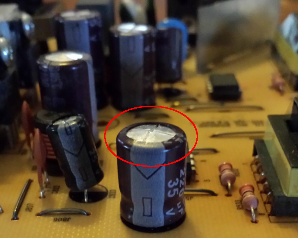
Example of a bad capacitor
Opening the monitor up and getting to the board was standard practice—the kind of thing many of us geeks started doing as soon as we were old enough to use a screwdriver. Whenever I take anything apart whether it's electronic, automotive, or household, I use my phone to take photos during the process to help remember how to put it back together. If you're trying this, be sure to do the same to document what type of screws go where and the direction of cabling. With the board in hand, it's easy to visually identify blown capacitors because they'll have a convex or rounded top as shown in these two photos. Since they're only a buck to a few bucks each, go ahead and replace any that you're unsure about. I actually found packs of 20 capacitors for $4.50 per pack on Amazon, but they take a few weeks to float across the ocean at that price.
The second photo provides some great points of reference. Contrast the convex top of the circled (bad) capacitor to the flat tops of the surrounding capacitors.
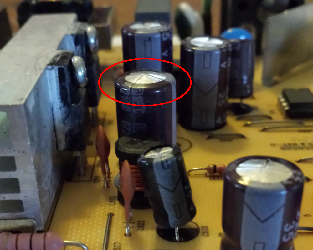
Another bad capacitor
Once you've identified any bad capacitors, there are a few things you should note before removing them. First, the caps in these photos have a light blue stripe on them (facing the front in the first image and facing right in the second). These are polarized caps meaning there's a positive and negative side to them as indicated by the negative sign (the rectangle) on the light stripe. If the caps you're replacing are polarized, pay attention to the direction they need to be reinserted. Second, each component on the board has an identifier or label such as C817. Those labels appear on each side of the board to help you locate the solder points on the opposite side of the component. Finally, each capacitor has 2 values on it: the capacitance and voltage. You'll need to jot those down along with the labels to ensure that you put the replacement capacitors back in the proper locations. If you're not sure what to buy for a replacement, you can find a guide online or take the bad caps to your local electronics shop and they'll know exactly what you need.
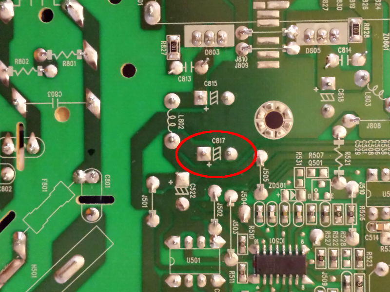
Capacitor label, symbol, and + marking
Now you're ready to remove the bad capacitors. Warm up your soldering iron and melt the solder for the caps according to the labels you noted previously. If you spend a few bucks on some desoldering braid, it can be used to "soak up" the heated solder making it easier to remove the caps without making a mess. When it's time to insert the new capacitors, remember to place the negative pin through the same hole as the previous one. The board should mark the negative positions by coloring them black on the component side of the board. Also, the positive hole is marked with a + symbol on the green side of the board as shown in the photo.

Fuse and warning
Of course, there could be other blown components besides capacitors, so inspect each of them to see if any appear to be burned out. It's common for monitors to contain a simple fuse that's cheap and easily replaceable. If your LCD won't turn on at all, look for a fuse as shown in the photo. You can remove the fuse and test it with a standard multimeter or a fuse tester. If it's defective, be sure to replace it with a fuse that has the same specifications as the warning states in the photo.
After soldering in the new capacitors, I reassembled the monitor and plugged it into my desktop. It started right up and worked great. A simple fix that only cost me $9 (including spare parts in case I need them later) allowed me to "upgrade" my secondary monitor from 1366x768 to 1440x900. On top of that, I was able to re-purpose the 1366x768 monitor as a secondary on the MacBook Pro for a total of 4 screens. It might not be a great monitor, but it's perfect for keeping an eye on a Webex meeting while I get real work done on another screen. Maybe I'll catch a tan with all this glow!
If you attempt a fix of your own—especially if it's a new experience for you or a big win—let me know how it goes in the comments.
